
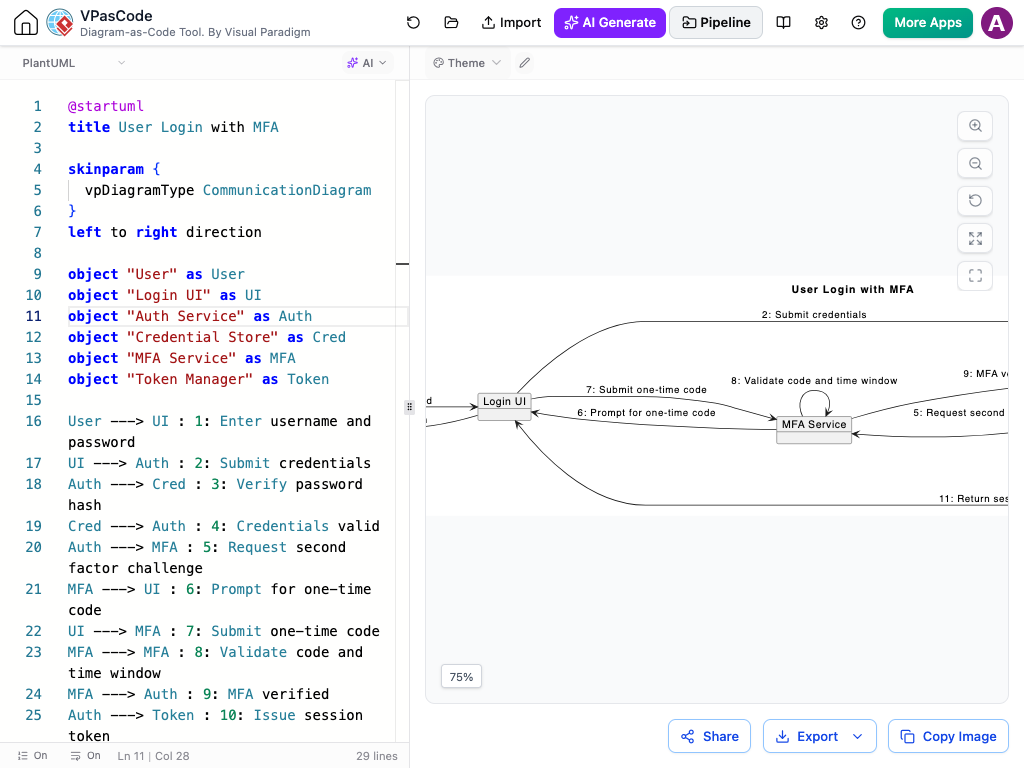
We have expanded VPasCode, Visual Paradigm’s diagram-as-code editor, with full rendering and editing support for UML Communication Diagrams.
Whether you are fine-tuning real-time message sequences between live microservices or documenting a complex application workflow, you can now write, edit, and instantly visualize Communication Diagrams using clean, text-based PlantUML code.

What is a UML Communication Diagram?
Formerly known as Collaboration Diagrams, UML Communication Diagrams highlight which system components interact and the order in which messages are exchanged. Unlike Sequence Diagrams, which focus on a vertical timeline, Communication Diagrams offer a spatial view of system relationships, making object dependencies and responsibilities much easier to analyze.
-
Code-First Efficiency: Write clean PlantUML scripts to define participating objects, communication links, and numbered message sequences.
-
Instant Visual Rendering: Preview your spatial layout directly alongside your code editor as you add or adjust interaction steps.
-
Version Control Ready: Keep your diagram source files directly inside your code repositories to maintain design documentation along with your code.
Example:
@startuml
title User Login with MFA

skinparam {
  vpDiagramType CommunicationDiagram
}
left to right direction

object "User" as User
object "Login UI" as UI
object "Auth Service" as Auth
object "Credential Store" as Cred
object "MFA Service" as MFA
object "Token Manager" as Token

User ---> UI : 1: Enter username and password
UI ---> Auth : 2: Submit credentials
Auth ---> Cred : 3: Verify password hash
Cred ---> Auth : 4: Credentials valid
Auth ---> MFA : 5: Request second factor challenge
MFA ---> UI : 6: Prompt for one-time code
UI ---> MFA : 7: Submit one-time code
MFA ---> MFA : 8: Validate code and time window
MFA ---> Auth : 9: MFA verified
Auth ---> Token : 10: Issue session token
Token ---> UI : 11: Return session token
UI ---> User : 12: Grant access to application

@enduml
Why Use Communication Diagrams & Who Are They For?
UML Communication Diagrams are an essential tool for software engineers, solution architects, and backend developers who need to map out component interactions during system design.
-
Focus on Structural Collaboration: Unlike Sequence Diagrams that prioritize a strict top-to-down timeline, Communication Diagrams highlight the network of relationships between live objects.
-
Trace Interaction Sequences: Numbered messages (
1: request(),2: update()) clarify execution order while keeping spatial dependencies obvious. -
Ideal for Microservice Architecture: Quickly identify tightly coupled services, overloaded controllers, or missing API gateway steps during design reviews.
👉 Learn more about the AI UML Communication Diagram Generator
Ready to visualize your service interactions?
Open VPasCode, paste your PlantUML script, and start mapping message flows and object dependencies in seconds.
👉 Try UML Communication Diagrams in VPasCode
Related posts:
 Transparency Meets Learning: Introducing “AI Fix Details” and Side-by-Side Code Diff
 Streamline Root-Cause Analysis and Execution with the New Solution Selection Matrix
 Introducing Enhanced Data Flow Diagram (DFD) Generation with Intelligent Layouts
 Custom AI Endpoint Support: Configure Your Preferred Provider for Visual Paradigm AI Agentic Features