


We are thrilled to announce the official launch of Visual Paradigm VPasCode, Visual Paradigm’s brand-new, unified diagram-as-code platform. Whether you are a software engineer, system architect, or business analyst, VPasCode is designed to streamline your workflow by transforming text into beautiful, professional diagrams in seconds.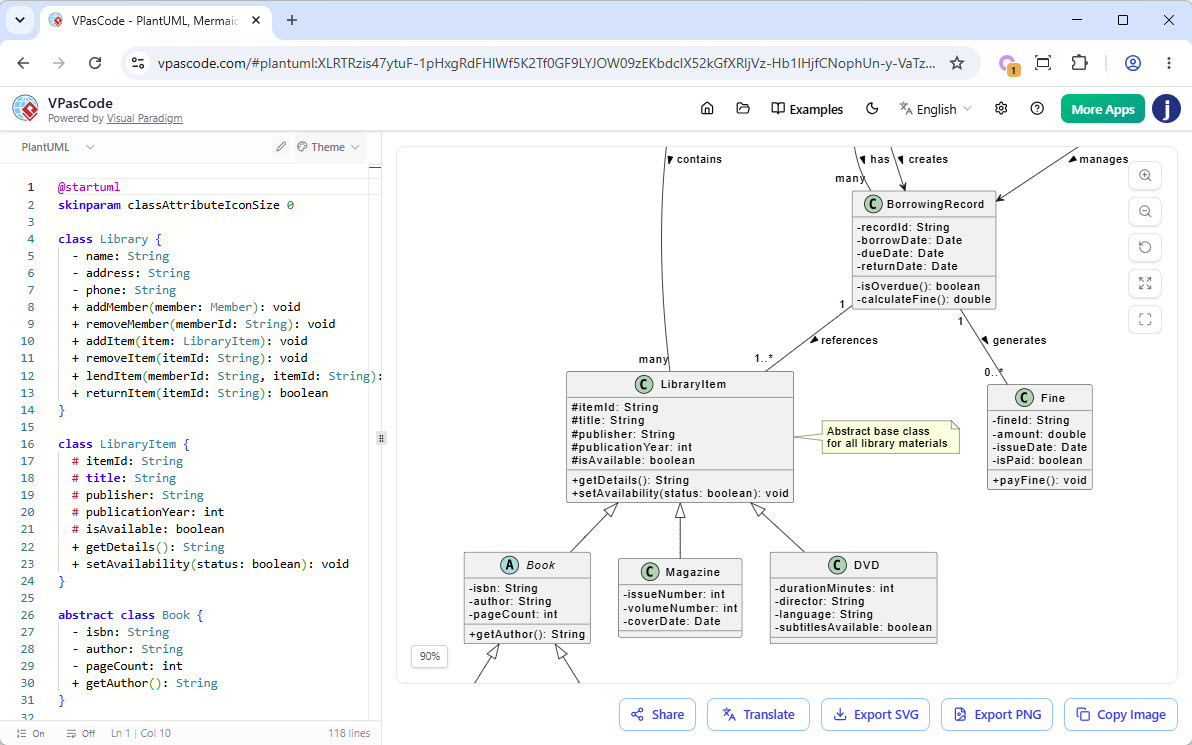
Say goodbye to context-switching between different tools. VPasCode brings your favorite open-source text-to-diagram languages together into a single, seamless, and powerful web-based environment.
What is VPasCode?
VPasCode (Visual Paradigm as Code) is an integrated environment that combines a convenient, free code editor with a high-performance diagram renderer. If you love the speed and version-control benefits of writing your diagrams, VPasCode gives you the ultimate sandbox to build, preview, and share them instantly.
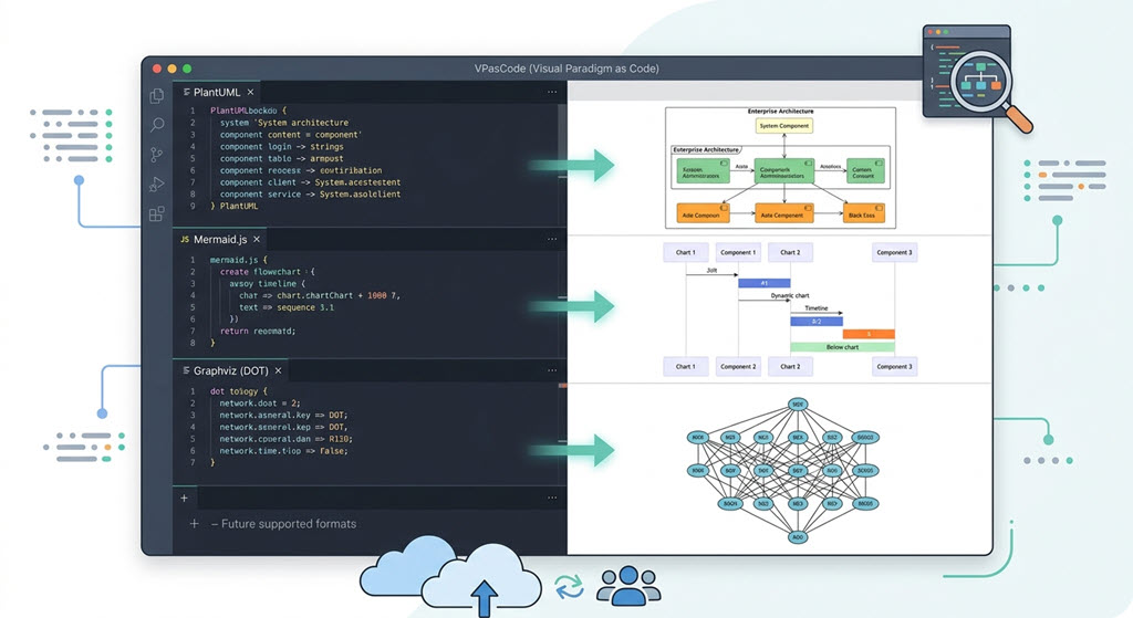
Because it is a fully integrated environment, VPasCode theoretically supports all syntax rules for the world’s most popular diagramming engines. At launch, we completely support:
- PlantUML Editor & Renderer: Create robust enterprise and software architecture diagrams.
- Mermaid.js Editor & Renderer: Render modern, markdown-inspired charts and timelines natively in your browser.
- Graphviz Editor & Renderer: Leverage the power of DOT language for complex network and data structures.
…and this is just the beginning! We will be continuously adding more text-to-diagram formats in the future.
Supported Diagram Types At a Glance
VPasCode supports an incredibly vast library of diagram types. Here is a snapshot of what you can build right now:
PlantUML Integration
- Sequence, Use Case, Class, and Object Diagrams
- Activity, Component, Deployment, and State Diagrams
- ArchiMate & C4 Models
- Entity Relationship Diagrams (ERD) & Chen ERD
- Network Diagrams, WBS (Work Breakdown Structure), and Timing Diagrams
Mermaid.js Integration
- Flowcharts, Class, and Sequence Diagrams
- Entity Relationship Diagrams (ERD) & State Diagrams
- Mind maps, Timelines, and User Journey Maps
- Gantt Charts, Git Graphs, and Kanban Boards
- C4 Models, Quadrant Charts, and Requirement Diagrams
Graphviz Integration
- Digraph & Graph
- Flowcharts & Data Flow Diagrams
- Organization Charts & Clusters
Features & Capabilities
We want VPasCode to be accessible to everyone, which is why we’ve packed our free tier with essential tools while offering groundbreaking AI-assisted features for premium users.
Free Features Available to Everyone:
- Multi-Engine Support: Full access to PlantUML, Mermaid.js, and Graphviz.
- Textual Descriptions: Create intricate diagrams purely through intuitive code.
- Real-Time Preview: See your diagram update instantly on the side of your screen as you type.
- Easy Sharing: Generate a unique URL to easily share your live diagram with teammates or clients.
- Flexible Exports: Download your finished work as high-quality PNG images or scalable SVG vector graphics.
Supercharge Your Workflow with Paid Features:
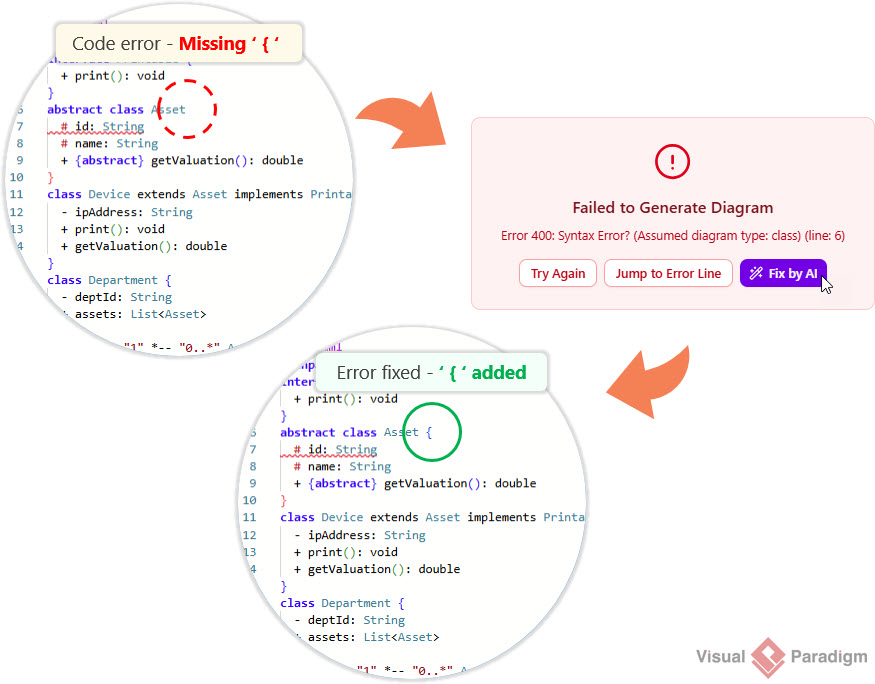
- AI Code Error Fixing: Stuck on a syntax error? Our built-in AI will analyze your PlantUML, Mermaid, or Graphviz code and fix errors automatically.
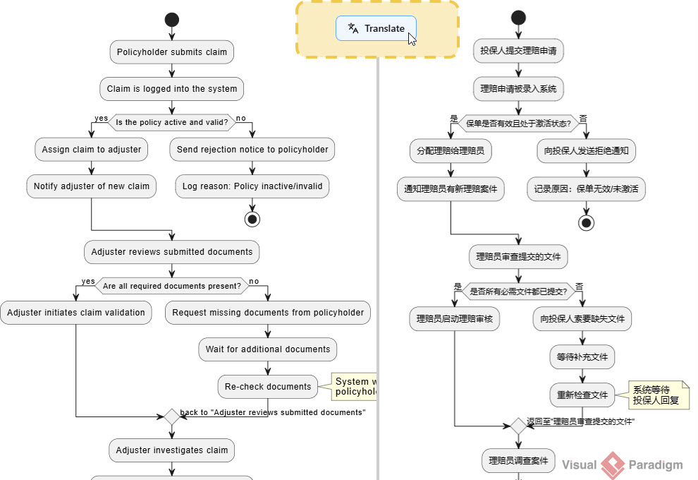
- AI Translation: Seamlessly translate the text and labels within your diagrams into multiple languages with a single click.
How to Access VPasCode Paid Features
If you are an existing Visual Paradigm user, you might already have access to our premium AI features!
The paid features of VPasCode are included with:
- Visual Paradigm Online Combo Edition (or higher).
- Visual Paradigm Desktop Professional Edition (or higher) with an active maintenance contract.
Note for Desktop Users: Visual Paradigm Professional Edition (or higher) users with active maintenance are automatically granted full access to the web apps of VP Online Combo Edition—which means you get instant access to VPasCode’s premium AI tools at no extra cost!
PlantUML and Mermaid in VPasCode – Diagram Examples
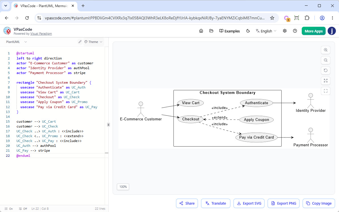
PlantUML Use Case Diagram: Ecommerce System
This use case diagram illustrates the primary interactions within an e-commerce checkout system. A customer can view their cart and proceed to checkout, where authentication, coupon application, and credit card payment are integrated through external services such as an identity provider and a payment processor.
@startuml
left to right direction
actor "E-Commerce Customer" as customer
actor "Identity Provider" as authPool
actor "Payment Processor" as stripe

rectangle "Checkout System Boundary" {
  usecase "Authenticate" as UC_Auth
  usecase "View Cart" as UC_Cart
  usecase "Checkout" as UC_Check
  usecase "Apply Coupon" as UC_Promo
  usecase "Pay via Credit Card" as UC_Pay
}

customer --> UC_Cart
customer --> UC_Check
UC_Check ..> UC_Auth : <>
UC_Check <.. UC_Promo : <>
UC_Check ..> UC_Pay : <>
UC_Auth --> authPool
UC_Pay --> stripe
@enduml
PlantUML Class Diagram: Library Management System
This class diagram models a library management system, showing the key entities involved in catalog management, member services, and lending operations. The design uses inheritance to represent different types of library materials (such as books, magazines, and DVDs), while associations between members, librarians, borrowing records, and fines illustrate how items are borrowed, returned, and managed throughout their lifecycle.
@startuml

class Library {
  - name: String
  - address: String
  - phone: String
  + addMember(member: Member): void
  + removeMember(memberId: String): void
  + addItem(item: LibraryItem): void
  + removeItem(itemId: String): void
  + lendItem(memberId: String, itemId: String): boolean
  + returnItem(itemId: String): boolean
}

class LibraryItem {
  # itemId: String
  # title: String
  # publisher: String
  # publicationYear: int
  # isAvailable: boolean
  + getDetails(): String
  + setAvailability(status: boolean): void
}

abstract class Book {
  - isbn: String
  - author: String
  - pageCount: int
  + getAuthor(): String
}

class EBook {
  - fileSizeMB: double
  - format: String
  - downloadUrl: String
  + download(): void
}

class PrintedBook {
  - shelfLocation: String
  - condition: String
  + getShelfLocation(): String
}

class Magazine {
  - issueNumber: int
  - volumeNumber: int
  - coverDate: Date
}

class DVD {
  - durationMinutes: int
  - director: String
  - language: String
  - subtitlesAvailable: boolean
}

class Member {
  - memberId: String
  - name: String
  - email: String
  - phone: String
  - membershipDate: Date
  + borrowItem(item: LibraryItem): boolean
  + returnItem(item: LibraryItem): boolean
  + getBorrowedItems(): List
}

class BorrowingRecord {
  - recordId: String
  - borrowDate: Date
  - dueDate: Date
  - returnDate: Date
  - isOverdue(): boolean
  - calculateFine(): double
}

class Fine {
  - fineId: String
  - amount: double
  - issueDate: Date
  - isPaid: boolean
  + payFine(): void
}

class Librarian {
  - staffId: String
  - department: String
  + processBorrowing(member: Member, item: LibraryItem): void
  + processReturn(item: LibraryItem): void
  + generateReport(): void
  + manageInventory(): void
}

' Inheritance relationships
LibraryItem <|-- Book
LibraryItem <|-- Magazine
LibraryItem <|-- DVD
Book <|-- EBook
Book <|-- PrintedBook

' Composition and Aggregation

Library "1" -- "many" Member : has >
Library "1" -- "many" LibraryItem : contains >
Library "1" -- "many" Librarian : employs >

Member "1" -- "many" BorrowingRecord : has >
BorrowingRecord "1" -- "1..*" LibraryItem : references >
BorrowingRecord "1" -- "0..*" Fine : generates >

' Association
Librarian --> BorrowingRecord : manages >
Member --> BorrowingRecord : creates >

note top of Library : Central system that manages\nmembers, items, and lending
note right of LibraryItem : Abstract base class\nfor all library materials
@enduml
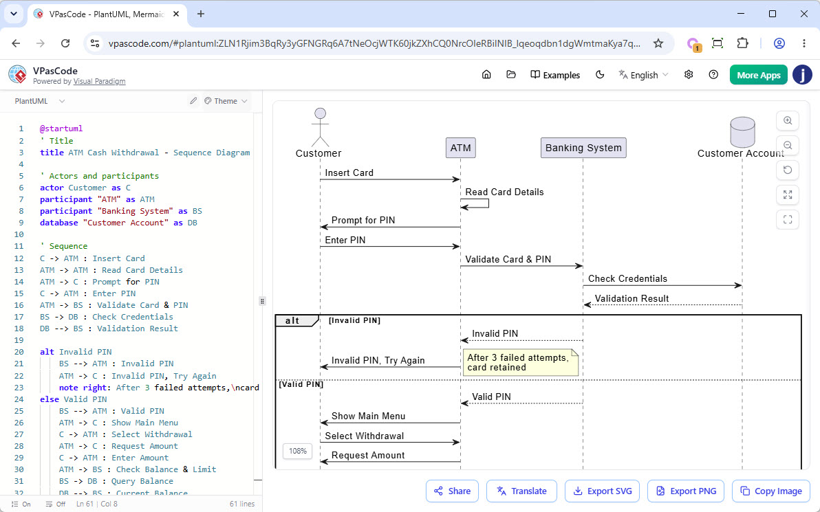
PlantUML Sequence Diagram: ATM Cash Withdraw
This sequence diagram illustrates the interactions involved in an ATM cash withdrawal transaction, from card insertion and PIN validation to cash dispensing and account updates. It highlights the communication between the customer, ATM, banking system, and customer account database, while also modeling alternative flows such as invalid PIN attempts, insufficient funds, and optional receipt printing.
@startuml
' Title
title ATM Cash Withdrawal - Sequence Diagram

' Actors and participants
actor Customer as C
participant "ATM" as ATM
participant "Banking System" as BS
database "Customer Account" as DB

' Sequence
C -> ATM : Insert Card
ATM -> ATM : Read Card Details
ATM -> C : Prompt for PIN
C -> ATM : Enter PIN
ATM -> BS : Validate Card & PIN
BS -> DB : Check Credentials
DB --> BS : Validation Result

alt Invalid PIN
    BS --> ATM : Invalid PIN
    ATM -> C : Invalid PIN, Try Again
    note right: After 3 failed attempts,\ncard retained
else Valid PIN
    BS --> ATM : Valid PIN
    ATM -> C : Show Main Menu
    C -> ATM : Select Withdrawal
    ATM -> C : Request Amount
    C -> ATM : Enter Amount
    ATM -> BS : Check Balance & Limit
    BS -> DB : Query Balance
    DB --> BS : Current Balance

    alt Insufficient Funds
        BS --> ATM : Insufficient Balance
        ATM -> C : Transaction Declined\n(Display Balance)
        C -> ATM : Cancel Transaction
        ATM -> C : Return Card
    else Sufficient Funds
        BS --> ATM : Approved
        ATM -> ATM : Dispense Cash
        ATM -> C : Dispense Cash
        C -> ATM : Take Cash
        ATM -> BS : Confirm Cash Dispensed
        BS -> DB : Debit Account & Log Transaction
        DB --> BS : Update Complete
        BS --> ATM : Transaction Complete
        ATM -> C : Print Receipt
        alt Receipt Requested
            C -> ATM : Take Receipt
        else No Receipt
            C -> ATM : Decline Receipt
        end
        ATM -> C : Return Card
        C -> ATM : Take Card
    end
end

ATM -> C : Thank You / Transaction End

@enduml
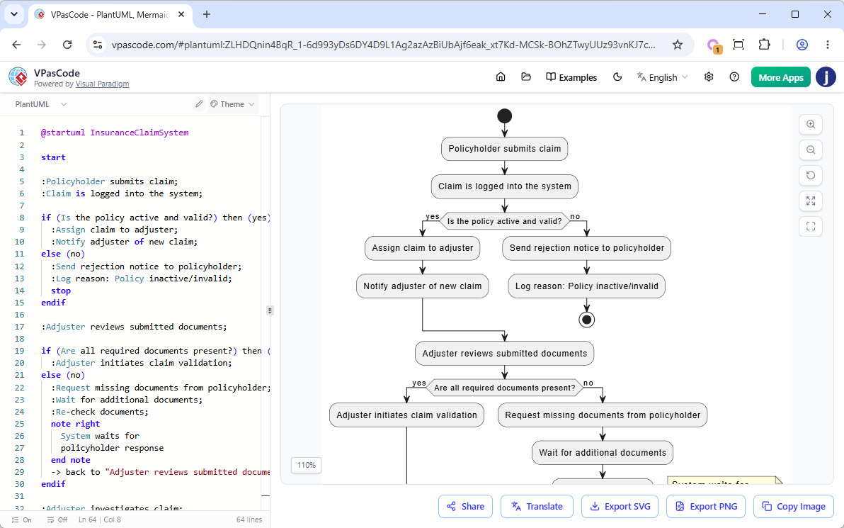
PlantUML Activity Diagram: Insurance Claim System
This activity diagram models the end-to-end workflow of an insurance claim processing system, from claim submission through validation, investigation, and settlement. It captures key decision points such as policy eligibility, document completeness, claim validity, and settlement acceptance, while illustrating both successful and exception-handling paths, including claim rejection and dispute resolution.
@startuml InsuranceClaimSystem

start

:Policyholder submits claim;
:Claim is logged into the system;

if (Is the policy active and valid?) then (yes)
  :Assign claim to adjuster;
  :Notify adjuster of new claim;
else (no)
  :Send rejection notice to policyholder;
  :Log reason: Policy inactive/invalid;
  stop
endif

:Adjuster reviews submitted documents;

if (Are all required documents present?) then (yes)
  :Adjuster initiates claim validation;
else (no)
  :Request missing documents from policyholder;
  :Wait for additional documents;
  :Re-check documents;
  note right
    System waits for
    policyholder response
  end note
  -> back to "Adjuster reviews submitted documents";
endif

:Adjuster investigates claim;
:Contact witnesses/experts if needed;
:Estimate damage/loss amount;

if (Is claim valid based on policy terms?) then (yes)
  :Calculate approved amount;
  :Apply deductible if applicable;
else (no)
  :Send rejection notice with reason;
  :Log decision in system;
  stop
endif

:Generate settlement offer;
:Send settlement offer to policyholder;

:Policyholder reviews offer;

if (Does policyholder accept the offer?) then (yes)
  :Process payment;
  :Update claim status to "Settled";
  :Send confirmation to policyholder;
  :Log closure details;
else (no)
  :Escalate to dispute resolution;
  :Negotiate settlement;
  :Update offer;
  -> back to "Send settlement offer to policyholder";
endif

stop

@enduml
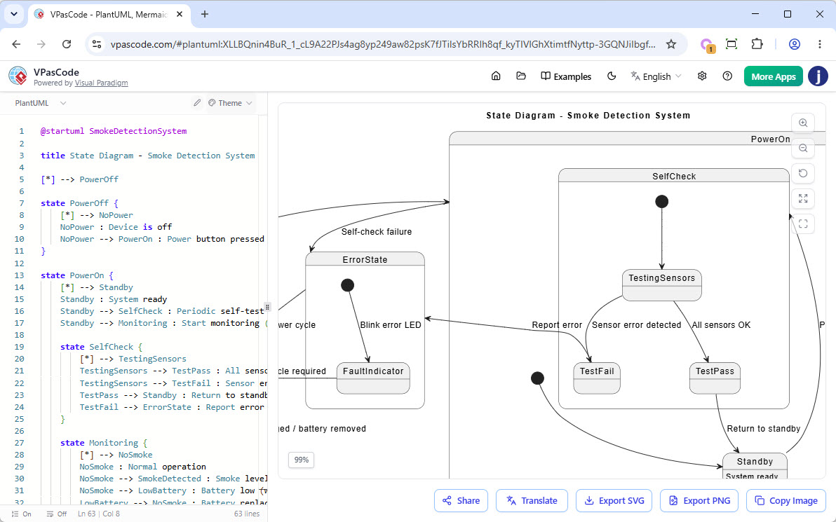
PlantUML State Diagram: Smoke Detection System
This state diagram illustrates the behavior of a smoke detection system as it transitions between operational states such as standby, monitoring, smoke detection, alarm activation, and error handling. It shows how the system responds to events including power changes, self-check results, smoke detection, low battery conditions, and user-initiated resets to ensure reliable fire monitoring and alerting.
@startuml SmokeDetectionSystem

title State Diagram - Smoke Detection System

[*] --> PowerOff

state PowerOff {
    [*] --> NoPower
    NoPower : Device is off
    NoPower --> PowerOn : Power button pressed
}

state PowerOn {
    [*] --> Standby
    Standby : System ready
    Standby --> SelfCheck : Periodic self-test (every 24h)
    Standby --> Monitoring : Start monitoring (sensor active)

    state SelfCheck {
        [*] --> TestingSensors
        TestingSensors --> TestPass : All sensors OK
        TestingSensors --> TestFail : Sensor error detected
        TestPass --> Standby : Return to standby
        TestFail --> ErrorState : Report error
    }

    state Monitoring {
        [*] --> NoSmoke
        NoSmoke : Normal operation
        NoSmoke --> SmokeDetected : Smoke level > threshold
        NoSmoke --> LowBattery : Battery low (wireless)
        LowBattery --> NoSmoke : Battery replaced

        state SmokeDetected {
            [*] --> InitialAlert
            InitialAlert --> ConfirmedSmoke : Smoke persists > 5 sec
            InitialAlert --> FalseAlarm : Smoke clears < 5 sec FalseAlarm --> NoSmoke : Reset
            ConfirmedSmoke --> AlarmActive
        }

        state AlarmActive {
            [*] --> SoundAlarm : Activate siren & lights
            SoundAlarm --> SendNotification : Notify control panel / app
            SendNotification --> WaitForReset
            WaitForReset --> AlarmActive : Smoke still present
            WaitForReset --> ResetSystem : Reset button pressed
            ResetSystem --> NoSmoke : System resets
        }
    }
}

state ErrorState {
    [*] --> FaultIndicator : Blink error LED
    FaultIndicator --> PowerOff : Manual power cycle required
}

PowerOn --> ErrorState : Self-check failure
ErrorState --> PowerOff : Power cycle

PowerOff --> [*] : System unplugged / battery removed

@enduml
PlantUML Component Diagram: Courier System
This component diagram presents the high-level architecture of a courier management system, showing how client applications, backend services, messaging infrastructure, caches, and databases interact to support parcel delivery operations. It illustrates the separation of responsibilities across services such as order management, dispatching, tracking, payments, notifications, and user management, while highlighting both synchronous API communication and asynchronous event-driven processing.
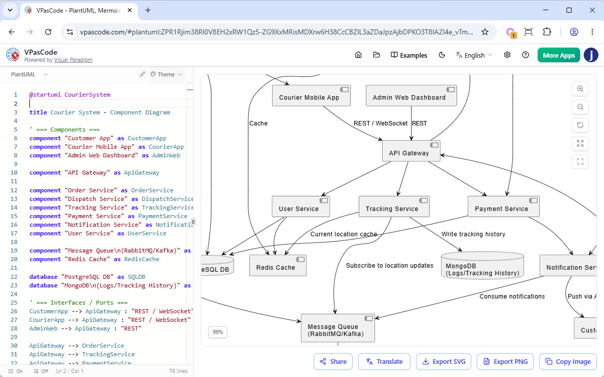
@startuml CourierSystem

title Courier System - Component Diagram

' === Components ===
component "Customer App" as CustomerApp
component "Courier Mobile App" as CourierApp
component "Admin Web Dashboard" as AdminWeb

component "API Gateway" as ApiGateway

component "Order Service" as OrderService
component "Dispatch Service" as DispatchService
component "Tracking Service" as TrackingService
component "Payment Service" as PaymentService
component "Notification Service" as NotificationService
component "User Service" as UserService

component "Message Queue\n(RabbitMQ/Kafka)" as MessageQueue
component "Redis Cache" as RedisCache

database "PostgreSQL DB" as SQLDB
database "MongoDB\n(Logs/Tracking History)" as MongoLogs

' === Interfaces / Ports ===
CustomerApp --> ApiGateway : "REST / WebSocket"
CourierApp --> ApiGateway : "REST / WebSocket"
AdminWeb --> ApiGateway : "REST"

ApiGateway --> OrderService
ApiGateway --> TrackingService
ApiGateway --> PaymentService
ApiGateway --> UserService

' === Service Dependencies ===
OrderService --> DispatchService : "gRPC / REST"
OrderService --> PaymentService
OrderService --> NotificationService
OrderService --> SQLDB : "JDBC"
OrderService --> RedisCache : "Cache"

DispatchService --> MessageQueue : "Publish events"
DispatchService --> CourierApp : "Push via API Gateway"
DispatchService --> SQLDB

TrackingService --> MessageQueue : "Subscribe to location updates"
TrackingService --> MongoLogs : "Write tracking history"
TrackingService --> RedisCache : "Current location cache"

PaymentService --> SQLDB
PaymentService --> NotificationService

NotificationService --> MessageQueue : "Consume notifications"
NotificationService --> CustomerApp : "Push via API Gateway"

UserService --> SQLDB
UserService --> RedisCache

' === Notes ===
note right of OrderService
  Handles parcel creation,
  pricing, and order status
end note

note right of DispatchService
  Matches orders with couriers,
  optimizes routes
end note

note bottom of MessageQueue
  Async events: order_created,
  location_updated,
  delivery_status_changed
end note

@enduml
PlantUML Deployment Diagram: Sample Architecture
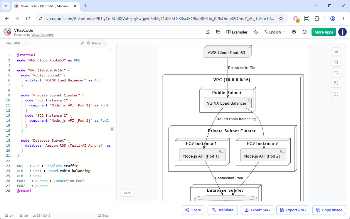
@startuml
node "AWS Cloud Route53" as DNS

node "VPC (10.0.0.0/16)" {
  node "Public Subnet" {
    artifact "NGINX Load Balancer" as ALB
  }

  node "Private Subnet Cluster" {
    node "EC2 Instance 1" {
      component "Node.js API [Pod 1]" as Pod1
    }
    node "EC2 Instance 2" {
      component "Node.js API [Pod 2]" as Pod2
    }
  }

  node "Database Subnet" {
    database "Amazon RDS (Multi-AZ Aurora)" as Aurora
  }
}

DNS --> ALB : Resolves traffic
ALB --> Pod1 : Round-robin balancing
ALB --> Pod2
Pod1 --> Aurora : Connection Pool
Pod2 --> Aurora
@enduml
PlantUML ArchiMate Example: Internet Browser
This ArchiMate diagram illustrates how business, application, and technology layers interact to support web-based business functionality through an internet browser. It demonstrates the relationships between business processes, dynamically generated web page components and data, browser services and plugins, and the underlying web server infrastructure that delivers and supports the application experience.
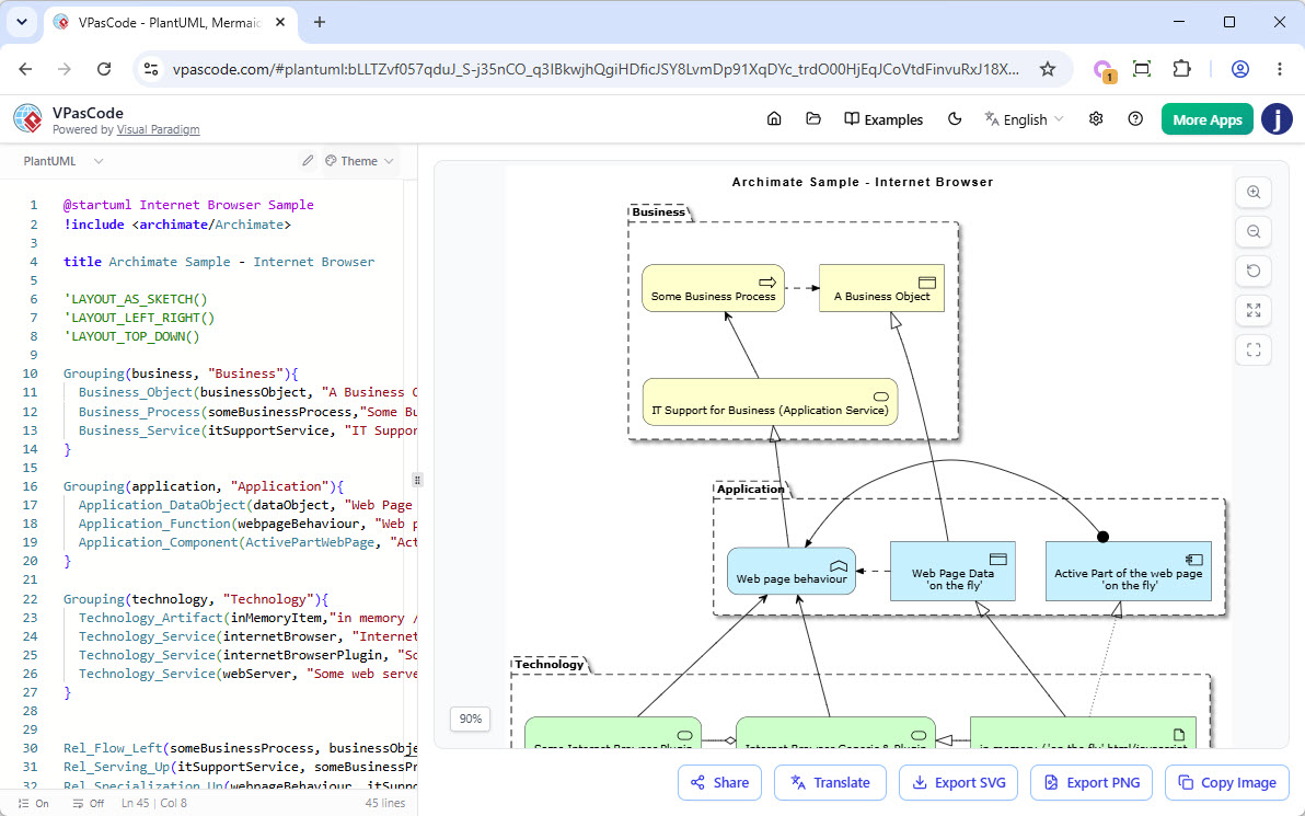
@startuml Internet Browser Sample
!include <archimate/Archimate>

title Archimate Sample - Internet Browser

'LAYOUT_AS_SKETCH()
'LAYOUT_LEFT_RIGHT()
'LAYOUT_TOP_DOWN()

Grouping(business, "Business"){
  Business_Object(businessObject, "A Business Object")
  Business_Process(someBusinessProcess,"Some Business Process")
  Business_Service(itSupportService, "IT Support for Business (Application Service)")
}

Grouping(application, "Application"){
  Application_DataObject(dataObject, "Web Page Data \n 'on the fly'")
  Application_Function(webpageBehaviour, "Web page behaviour")
  Application_Component(ActivePartWebPage, "Active Part of the web page \n 'on the fly'")
}

Grouping(technology, "Technology"){
  Technology_Artifact(inMemoryItem,"in memory / 'on the fly' html/javascript")
  Technology_Service(internetBrowser, "Internet Browser Generic & Plugin")
  Technology_Service(internetBrowserPlugin, "Some Internet Browser Plugin")
  Technology_Service(webServer, "Some web server")
}


Rel_Flow_Left(someBusinessProcess, businessObject, "")
Rel_Serving_Up(itSupportService, someBusinessProcess, "")
Rel_Specialization_Up(webpageBehaviour, itSupportService, "")
Rel_Flow_Right(dataObject, webpageBehaviour, "")
Rel_Specialization_Up(dataObject, businessObject, "")
Rel_Assignment_Left(ActivePartWebPage, webpageBehaviour, "")
Rel_Specialization_Up(inMemoryItem, dataObject, "")
Rel_Realization_Up(inMemoryItem, ActivePartWebPage, "")
Rel_Specialization_Right(inMemoryItem,internetBrowser, "")
Rel_Serving_Up(internetBrowser, webpageBehaviour, "")
Rel_Serving_Up(internetBrowserPlugin, webpageBehaviour, "")
Rel_Aggregation_Right(internetBrowser, internetBrowserPlugin, "")
Rel_Access_Up(webServer, inMemoryItem, "")
Rel_Serving_Up(webServer, internetBrowser, "")

@enduml
PlantUML ERD Example: Cinema Ticket System
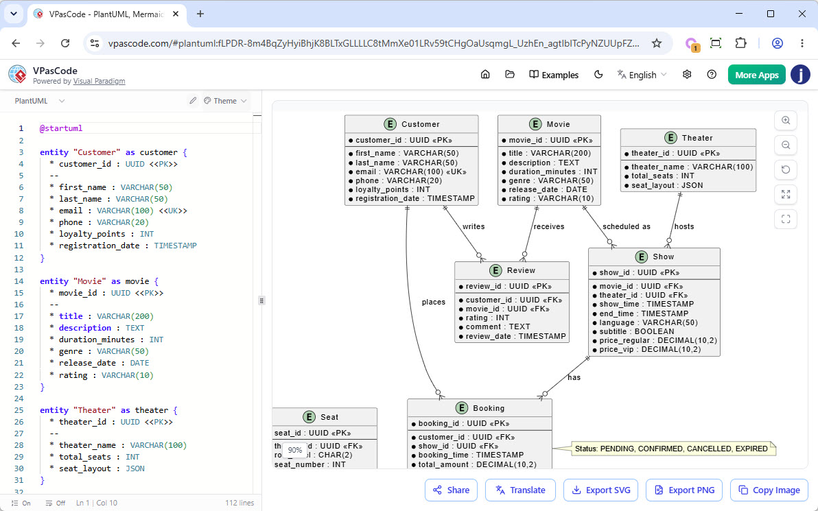
@startuml

entity "Customer" as customer {
  * customer_id : UUID <>
  --
  * first_name : VARCHAR(50)
  * last_name : VARCHAR(50)
  * email : VARCHAR(100) <>
  * phone : VARCHAR(20)
  * loyalty_points : INT
  * registration_date : TIMESTAMP
}

entity "Movie" as movie {
  * movie_id : UUID <>
  --
  * title : VARCHAR(200)
  * description : TEXT
  * duration_minutes : INT
  * genre : VARCHAR(50)
  * release_date : DATE
  * rating : VARCHAR(10)
}

entity "Theater" as theater {
  * theater_id : UUID <>
  --
  * theater_name : VARCHAR(100)
  * total_seats : INT
  * seat_layout : JSON
}

entity "Show" as show {
  * show_id : UUID <>
  --
  * movie_id : UUID <>
  * theater_id : UUID <>
  * show_time : TIMESTAMP
  * end_time : TIMESTAMP
  * language : VARCHAR(50)
  * subtitle : BOOLEAN
  * price_regular : DECIMAL(10,2)
  * price_vip : DECIMAL(10,2)
}

entity "Seat" as seat {
  * seat_id : UUID <>
  --
  * theater_id : UUID <>
  * row_label : CHAR(2)
  * seat_number : INT
  * seat_type : VARCHAR(20)
  * is_accessible : BOOLEAN
}

entity "Booking" as booking {
  * booking_id : UUID <>
  --
  * customer_id : UUID <>
  * show_id : UUID <>
  * booking_time : TIMESTAMP
  * total_amount : DECIMAL(10,2)
  * status : VARCHAR(20)
  * payment_method : VARCHAR(30)
  * transaction_id : VARCHAR(100)
}

entity "BookingSeat" as booking_seat {
  * booking_id : UUID <<FK,PK>>
  * seat_id : UUID <<FK,PK>>
  --
  * ticket_price : DECIMAL(10,2)
  * discount_applied : DECIMAL(10,2)
}

entity "Payment" as payment {
  * payment_id : UUID <>
  --
  * booking_id : UUID <>
  * amount : DECIMAL(10,2)
  * payment_date : TIMESTAMP
  * payment_status : VARCHAR(20)
  * payment_gateway : VARCHAR(30)
  * gateway_reference : VARCHAR(200)
}

entity "Review" as review {
  * review_id : UUID <>
  --
  * customer_id : UUID <>
  * movie_id : UUID <>
  * rating : INT
  * comment : TEXT
  * review_date : TIMESTAMP
}

' Relationships
customer ||--o{ booking : "places"
movie ||--o{ show : "scheduled as"
theater ||--o{ show : "hosts"
show ||--o{ booking : "has"
booking ||--|{ booking_seat : "contains"
seat ||--o{ booking_seat : "assigned to"
booking ||--|| payment : "has"
customer ||--o{ review : "writes"
movie ||--o{ review : "receives"

note right of booking : Status: PENDING, CONFIRMED, CANCELLED, EXPIRED
note left of seat : seat_type: REGULAR, VIP, COUPLES
note right of payment : payment_status: PENDING, SUCCESS, FAILED, REFUNDED

@enduml
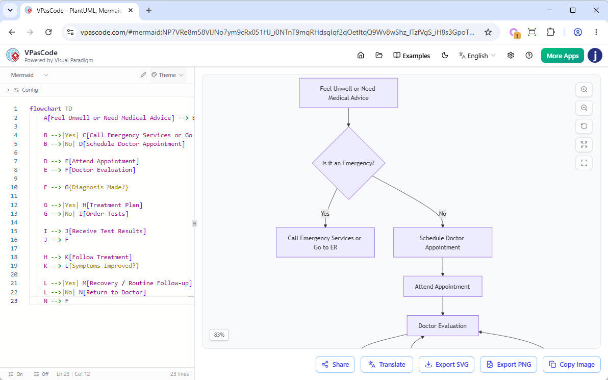
Mermaid Flowchart: See Doctor
This flowchart illustrates a typical healthcare decision-making process, guiding patients from the initial recognition of symptoms through diagnosis, testing, treatment, and recovery. It highlights key decision points, including emergency assessment, diagnostic evaluation, and treatment effectiveness, while showing how unresolved symptoms may require additional medical consultation and reassessment.
flowchart TD
    A[Feel Unwell or Need Medical Advice] --> B{Is it an Emergency?}

    B -->|Yes| C[Call Emergency Services or Go to ER]
    B -->|No| D[Schedule Doctor Appointment]

    D --> E[Attend Appointment]
    E --> F[Doctor Evaluation]

    F --> G{Diagnosis Made?}

    G -->|Yes| H[Treatment Plan]
    G -->|No| I[Order Tests]

    I --> J[Receive Test Results]
    J --> F

    H --> K[Follow Treatment]
    K --> L{Symptoms Improved?}

    L -->|Yes| M[Recovery / Routine Follow-up]
    L -->|No| N[Return to Doctor]
    N --> F
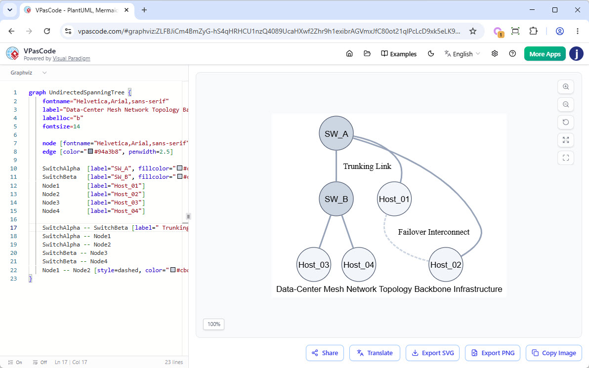
Graphviz Graph
This diagram represents a simplified data-center network topology, illustrating how hosts are connected through a backbone of interconnected switches. It highlights the primary communication paths between network devices, including a trunk link between switches and a secondary failover connection that provides redundancy and resilience in the event of network disruptions.
graph UndirectedSpanningTree {
    fontname="Helvetica,Arial,sans-serif"
    label="Data-Center Mesh Network Topology Backbone Infrastructure"
    labelloc="b"
    fontsize=14

    node [fontname="Helvetica,Arial,sans-serif", shape=circle, style=filled, color="#475569", fillcolor="#f1f5f9", width=0.8, fixedsize=true]
    edge [color="#94a3b8", penwidth=2.5]

    SwitchAlpha  [label="SW_A", fillcolor="#cbd5e1"]
    SwitchBeta   [label="SW_B", fillcolor="#cbd5e1"]
    Node1        [label="Host_01"]
    Node2        [label="Host_02"]
    Node3        [label="Host_03"]
    Node4        [label="Host_04"]

    SwitchAlpha -- SwitchBeta [label=" Trunking Link", weight=5]
    SwitchAlpha -- Node1
    SwitchAlpha -- Node2
    SwitchBeta -- Node3
    SwitchBeta -- Node4
    Node1 -- Node2 [style=dashed, color="#cbd5e1", label=" Failover Interconnect"]
}
Get Started Today
Ready to experience the speed of diagram-as-code? Whether you need a reliable PlantUML editor, a fast Mermaid editor, or a powerful Graphviz compiler, VPasCode is ready for you.
Head over to our platform now at:
Try out the real-time editor, and revolutionize the way you design software and systems!